🔄 PWM (Pulse Width Modulation) is a technique used to control the power delivered to electronic components like LEDs, motors, and buzzers. One of the most important aspects of PWM is the duty cycle—the percentage of time a signal stays ON during one cycle.
In this article, you’ll learn what duty cycle means, how to calculate it, and how to use it in your electronics projects. We’ve also included a calculator to make it even easier.
🔄 PWM Duty Cycle Calculator
🔗 Powered by Orbit6.com
🙋♀️ What Is PWM Duty Cycle?
The duty cycle of a PWM signal is the proportion of time the signal is in the “ON” state during a single PWM period. It’s usually expressed as a percentage.
- A 100% duty cycle means the signal is always ON
- A 0% duty cycle means it’s always OFF
- A 50% duty cycle means it’s ON half the time
This directly affects the average power delivered to the load.
🧮 Duty Cycle Formula
You can calculate the duty cycle using this formula:
Duty Cycle (%) = (Pulse Width / Period) × 100Where:
- Pulse Width = duration of the HIGH signal (in microseconds, ms, or seconds)
- Period = total duration of one PWM cycle
You can also find the period using frequency:
Period = 1 / Frequency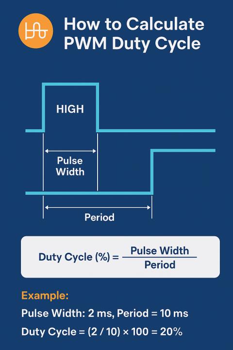
⚡ Example
If the pulse width is 2 milliseconds and the PWM period is 10 milliseconds:
Duty Cycle = (2 / 10) × 100 = 20%So the signal is ON for 20% of each cycle.
📊 Why Duty Cycle Matters
The duty cycle determines how much power is delivered to a device:
- For a DC motor, a higher duty cycle = more speed
- For an LED, a higher duty cycle = brighter light
- For a heater, a higher duty cycle = more heat
✨ Tips for Better PWM Control
- Use a high enough frequency to avoid flickering in lights or noise in motors
- Tune duty cycle to match load requirements
- Watch for thermal effects in high-power applications